Core Features
Power & Net Management
ProtoFlow provides comprehensive power and ground symbols, net label management, and automatic net connectivity analysis for reliable circuit design.
# Power Symbols
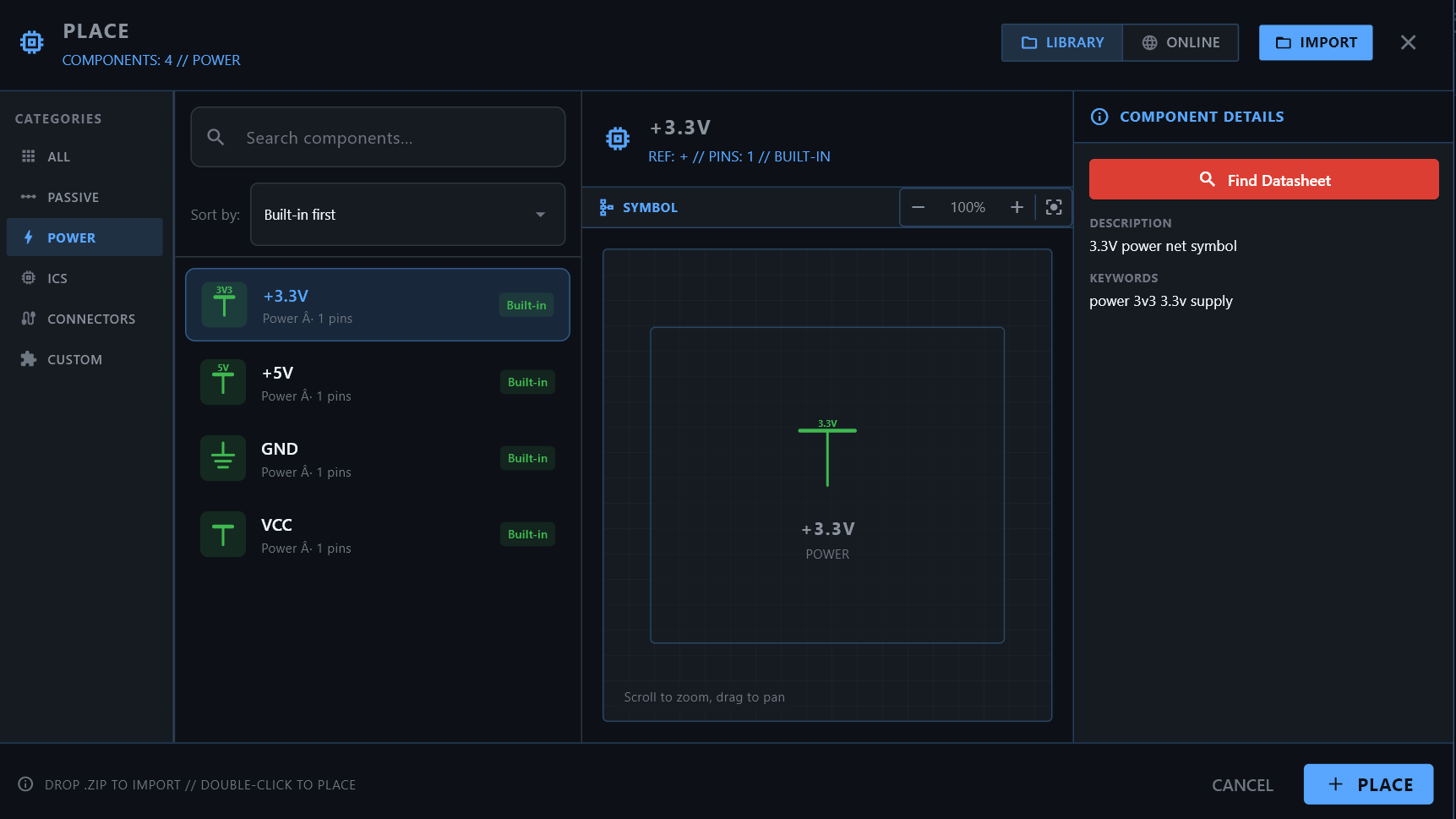
Power symbols represent voltage rails in your schematic. ProtoFlow includes a comprehensive set of standard power symbols that can be placed directly on pins or wires.
Available Power Symbols
| Symbol | Net Name | Typical Use |
|---|---|---|
| VCC | VCC | Generic positive supply |
| 5V | +5V | 5-volt rail |
| 3.3V | +3V3 | 3.3-volt rail |
| 12V | +12V | 12-volt rail |
| -5V | -5V | Negative 5-volt rail |
| -12V | -12V | Negative 12-volt rail |
| VDD | VDD | Positive supply (CMOS convention) |
| VSS | VSS | Negative supply (CMOS convention) |
| VBAT | VBAT | Battery supply |
| VBUS | VBUS | USB bus power |
| PWR_FLAG | PWR_FLAG | Power source indicator for ERC |
# Ground Symbols
Multiple ground types are available to distinguish between different ground domains in your design.
| Symbol | Net Name | Typical Use |
|---|---|---|
| GND | GND | General digital ground |
| GND_PWR | GND_PWR | Power ground (high current) |
| GNDA | GNDA | Analog ground (sensitive signals) |
| Earth GND | EARTH | Chassis / earth ground |
| Chassis GND | CHASSIS | Enclosure ground |
| Signal GND | SGND | Signal-level ground |
Best Practice
Use separate ground symbols for analog and digital sections. This helps during PCB layout when you need to manage ground planes and avoid noise coupling.
# Net Labels
Net labels allow you to name wires and create connections between distant points on your schematic without drawing long wires.
How to Place Net Labels
- Press L to activate the net label tool
- Click on a wire or pin to place the label
- Type the net name in the label editor
- Press Enter to confirm
Net Label Features
- Automatic naming — ProtoFlow auto-assigns net names to unnamed nets
- Cross-sheet connectivity — Two net labels with the same name on different parts of the schematic (or different sheets) are electrically connected
- Label editing — Double-click a label to rename it. All connected labels update automatically.
- Bus support — Use bus notation for grouped signals (e.g., DATA[0..7])
- AI connection style — When the AI creates connections, you can configure it to prefer direct wires or net labels via AI settings
# Net Connectivity Analysis
ProtoFlow automatically analyzes net connectivity to build a complete netlist from your schematic.
How It Works
- Automatic extraction — Nets are extracted in real-time as you draw wires and place components
- Automatic traversal — The analysis starts from each pin and follows all connected wires and labels to discover the full net
- Floating pin detection — Pins that aren't connected to any net are flagged as potential errors
- Short circuit detection — Multiple power nets connected together are flagged
- Hierarchy view — The Hierarchy panel shows all detected nets and the pins connected to each one
Viewing Nets
Open the Hierarchy panel from the activity bar. It displays a searchable tree view of all components and nets in your schematic. Click on a net to highlight all connected elements on the canvas.
Hierarchy panel showing nets and connected components with search functionality
Next Steps
- → Run Design Analysis to validate your nets
- → Generate a Bill of Materials
- → Learn about AI Copilot net management